1. Summary
Waste incineration can reduce, recycle and make harmless waste treatment, and recover its heat for power generation and heating. Garbage incineration has become the main way of garbage disposal in some developed countries. This garbage incineration power plant is a total investment of 410 million yuan garbage incineration power plant in Guangdong Province and Canada, covering an area of more than 30,000 square meters. There are four incinerators, four waste heat boilers and two 6MW turbine generators. The four production lines are designed to dispose of 600 tons of garbage per day. The annual power generation capacity is 8797 kWh. A ton of garbage can generate no less than 300 KWh of electricity.

The core technology of this project is the third generation of CAPS technology in the world, namely the gas-controlled solid waste thermal decomposition technology. Four CAPS pyrolysis furnaces have been built by using this technology. The steam generated by four waste heat boilers is supplied to two 6MW steam turbines to generate electricity, which really realizes the conversion of waste into resources.
Two. Refuse incinerators and related equipment
The garbage incinerator in this garbage incineration plant is a forward-push, multi-stage mechanical grate incinerator made in Canada. The third generation of gas-controlled solid waste thermal decomposition technology (CAPS) has been applied in the incinerator, which can effectively reduce the toxic gases produced by incineration.
1. garbage bin structure
The garbage is transported to the treatment plant after being transported to the garbage bin. The new trash can be stored in the warehouse for 3 days and then can be burned in the furnace. After fermentation and leachate discharge, the calorific value of the garbage can be increased and the garbage can be easily ignited. In the warehouse, the garbage can be sent to the front hopper with a crane grab.
2. combustion chamber and incinerator grate structure
The refuse incinerator is a reciprocating, pushing and multistage mechanical grate incinerator. The incinerator consists of a feeder and eight combustion grate units, including two-stage grate in the drying section, four-stage grate in the gasification combustion section and two-stage grate in the burnout section. The temperature inside the incinerator is controlled within 700 C. The burnt out waste from the last stage grate left the incinerator and fell into the ash bin.
1) feeder and fire door.
The feeder is pushed into the combustion chamber from the fire door through the feeder (Loading Ram). The feeder is only responsible for feeding, providing no combustion air and isolation from the combustion zone through the fire door. The fire door remains closed when the feeder is retracted. Closing the fire door can separate the furnace from the outside and maintain the negative pressure inside the furnace. At the same time, there is a temperature measuring point at the entrance of the combustion chamber. When the garbage temperature of the inlet of the combustor is too high, the solenoid valve will control the sprayer sprayed after the fire door to prevent the rubbish from the feeding chute from igniting the garbage in the hopper when the fire door opens.
2) combustion grate
The eight stage combustion grate is divided into two stages: dry grate, four stage gasifying combustion grate and two stage burnout section. Each stage of the grate is equipped with a hydraulic driven pulse pushing device. The 8-stage pushing device (pusher) pushes the garbage in a certain order, so that the garbage entering the incinerator is pushed to the next grate by the pusher in coordination with the various grates. Evenly distributed holes on the grate are used to discharge the primary air needed for combustion. The primary air supplied for combustion is supplied by a primary air duct below the grate. In the process of grate pushing, refuse is subjected to heat radiation from burner and furnace, and is blown by primary air. Moisture evaporates rapidly and burns on fire.
3) burner layout
There are two main combustors in the combustion chamber, as shown in figures two 17, 18. There are temperature measuring points above the combustion grate in the incinerator. When the incinerator is started up and the combustion temperature is below the requirement, the burner 17 feeds oil to support combustion. Burner 18 is located at the outlet of the furnace for reburning unburned refuse. The air required for the burner is supplied by a combustion fan common to four incinerators (as shown in Figure 27). The air required for the burner to burn is clean air inhaled by the atmosphere. When the combustion fan fails or the air supply is insufficient, the partial air supply of the fan is supplied to the burner by the bypass (shown in Fig. 26).
3. two combustion chamber flue
Two the main part of the combustion chamber is a cylindrical flue, and there is no smoke angle caused by pipes. The purpose of setting the secondary combustion chamber is to make the flue gas stay more than 2S at about 1000 C under the theoretical air volume of 120 ~ 130%, so that the harmful gas can be decomposed in the furnace. There is a secondary burner at the entrance of the secondary combustion chamber. When the system detects that the smoke temperature at the exit of the secondary combustion chamber is less than a certain value, the secondary combustion will be ignited. The two wind enters the two combustion chamber at the entrance of the two combustion chamber. The secondary combustion chamber has two outlets leading to the waste heat boiler, and each outlet has a hydraulically driven baffle to control the flue gas entering.
4. one or two winds system
Each incinerator is equipped with a blower. The blower sucks air from the garbage dump and also sucks gas leaking from the lower part of the chamber pusher to the outside of the incinerator. This arrangement of air supply is to ensure that the garbage bin is in a state of micro-negative pressure, to avoid gas leakage from the garbage bin. The air supply enters the waste heat boiler, passes through the two-stage air preheater of the waste heat boiler and enters a large mixing header (Fig. 221). Then it enters the primary combustion chamber and the secondary combustion chamber of the incinerator as one and two secondary air respectively. The header can also accept the air supply from the bypass of the exhaust heat boiler. The primary air leaving the header is divided into two pipelines: pipeline 1 (fig. 210-1) leads to three ducts for air supply to the 1-3 grate, and another pipeline 2 (fig. 210-2) leads to five ducts for air supply to the 4-8 grate. The primary air supply to the grate can dry garbage, cool the grate and supply the air needed for combustion. The air volume control valve on line 1 should be adjusted according to the temperature of the inlet of the incinerator. The air volume control valve on line 2 should be adjusted according to the temperature and oxygen content of the furnace. The air volume in the furnace should be 70~80% of theoretical air volume. The two wind goes through the pipeline (Fig. two 25) to the two chamber. The two wind supply is 120~130% of theoretical air volume.
5. row ash system
The ash discharged from the incinerator falls into the ash tank. The arrangement direction of the two parallel ash troughs is perpendicular to the arrangement direction of the incinerator, and the ash troughs of the four incinerators are transversely connected. The hydraulically driven ash separator (Fig. two, 23) selects ash to fall into a certain ash tank. Ash conveyor belt at the bottom of the ash tank is responsible for transporting four slag from the incinerator to the ash tank. Ash trough is required to ensure that there is a certain level of water to immerse ash.
6. flue gas treatment equipment
The flue gas discharged from the waste heat boiler enters the semi-dry gas scrubber first, and the slaked lime slurry is sprayed into the tower by atomizer from the top of the tower to neutralize the acidic gas in the flue gas, which can effectively remove HC.

Schematic diagram of garbage incinerator for refuse incineration power plant
1. Air from the garbage bin 2. Clean air inhaled by the blower 3. Air leaked under the pusher 4. Hopper 5. Air inlet of the burner 6. Partial air supplied by the blower from other incinerators 7. Fan 8. Blower 9. Small mixing header and bypass air valve 10. Furnace exhaust air main pipe 10-1. Front main air valve 110-2. Back main air valve 211. Manual valve 12. Pneumatic valve 13. Air supply pipe 14. Feeder 15. First combustion chamber 16. Second combustion chamber 17. Main burner 118. Main burner 219. Secondary burner 20. Flue gas outlet hydraulic baffle 21. Air large mixing header 22. Waste heat boiler 23. Gas scrubber 24. Bag filter 25. Fire door 26. Cooling water 27. Outlet cooling device A. Cooling water inlet B. Cooling water outlet C. Spray water D. Cooked lime supply E. Compressed air.
Three, refuse incineration power plant waste incinerator in the advantages of pollutant control
Dioxins in domestic waste incineration flue gas is a common concern in the world in recent years. Dioxins have caused great harm to the environment. Effective control of the generation and diffusion of dioxins is directly related to the promotion and application of waste incineration and waste power generation technology.
1. the structure of dioxins
The molecular structure of dioxins is 1 or 2 oxygen atoms connecting 2 benzene rings substituted by chlorine. Two oxygen atoms are linked called polychlorinated dibenzo-p-dioxin (PCDD), and one oxygen atom is called polychlorinated dibenzo-furan (PCDF). Collectively referred to as dioxin (dioxin). The most toxic 2,3,7,8-PCDD is 1000 times more toxic than potassium cyanide. Dioxin is highly toxic to mammals, soluble in water and good in thermal stability.

2. generation principle of dioxin in waste incinerator
The sources of dioxins in incinerators are petroleum products and chlorinated plastics, which are the precursors of dioxins. The main way of production is combustion generation. There are a lot of NaCl, KCl and so on in domestic waste, and S elements are often produced in incineration. And salts containing Cl elements react to form HCl when there is oxygen. HCl is also generated by the CuO reaction generated by oxidation of Cu. The study found that the final catalyst for dioxin production is the C element (CO).
3. Superiority of Incinerator with Gas Controlled Solid Waste Thermal Decomposition Technology in Suppressing Dioxin Production
Gas-controlled pyrolysis incinerator divides the incineration process into two combustion chambers, the first combustion chamber for waste thermal decomposition temperature is controlled within 700 C, so that the waste decomposes at low temperature under anoxic conditions, when metal elements such as Cu, Fe, Al will not be oxidized, so there will not be some, will greatly reduce the amount of dioxins; L production is affected by residual oxygen concentration, so anoxic combustion can reduce the production of HCl, and it is difficult to generate a large number of HCl in self-reducing atmosphere. Because the gas-controlled waste incinerator is a solid bed, it will not produce smoke and dust, and there will be no unburned carbon residue into the secondary combustion chamber. The combustible components in the garbage are decomposed into combustible gases, and two oxygen chambers with sufficient oxygen are used to burn. The temperature of the secondary combustion chamber is about 1000 C and the flue length makes the flue gas stay more than 2s, which ensures the complete decomposition and combustion of toxic organic gases such as dioxins at high temperature.
In addition, the use of bag filter avoids the use of electrostatic precipitation of Cu, Ni, Fe particles on the formation of dioxins catalysis.
Four. Waste heat boiler equipment
The waste heat boiler of refuse incineration power plant is flue-type waste heat boiler. The flue gas flow direction is changed five times in the boiler. Boiler pressure 4MPa, evaporation 15t/h. The structure of HRSG is shown below. Water walls are arranged in the furnace, flue and high temperature flue gas inlet.
1. flue gas flow
As shown in Figure 4, flue gas enters the waste heat boiler from the secondary combustion chamber of the incinerator through the upper or lower flue (flue gas passes through the lower part without passing through the water wall K). First, it passes through the second stage superheater E, the first stage superheater F, the second stage air preheater G, and then enters the main furnace from the lower part and exchanges heat with the water wall. After changing the angle at the upper outlet of the furnace, it passes through the first economizer I, the first air preheater H and the second economizer J in turn, and the flue gas leaves the waste heat boiler from the flue N.
2. air supply process
As shown in Figure 4, the air coming from the blower enters the waste heat boiler through pipeline A, passes through two stages of air preheater H and G heat exchange in the furnace, and then leaves the boiler through the pipeline.
3. soda process
As shown in Fig. 4, the feed water at 145 C passes through two economizers J and I (the economizer is equipped with a feed water bypass), enters the boiler drum L and the supercooled water in the drum from the descending tube into the lower header, is heated by the water wall in the furnace at a constant pressure under 4 MPa, and the steam enters the two superheaters F and E at 400 C, leaving the boiler and enters the steam main tube.

Structure diagram of waste heat boiler
A. air supply inlet pipe B. air supply outlet pipe C. upper high temperature flue D. lower flue E. secondary superheater F. first superheater G. second air preheater H. first air preheater I. second economizer J. first economizer K. water wall L. drum M. header
Five. Turbo generator sets and auxiliaries system
The four waste heat boiler of MSW incineration power plant is equipped with two steam turbines. The main steam system adopts centralized master control, and two turbo generators are arranged longitudinally in the workshop. The steam turbine adopts 6MW condensing steam turbine produced by Guangzhou Scot. Design inlet pressure 3.9MPa, inlet temperature 390 degree, rated steam 35t/h.
The unit is equipped with two stage steam ejector and first stage gland seal air ejector. Design a primary air supply deaerator. The condensing mode of the unit is water cooling, and the mechanical ventilation cooling tower is the two cycle water cooling system. The circulating water flow is guaranteed by the circulating water pump. The circulating water system is cooled by the air cooler and the lubricating oil station simultaneously. The condensate water enters the deaerator through the condensing pump through the steam seal heater. The low pressure feedwater at the outlet of the deaerator is boosted through the feed water pump and then enters the waste heat boiler. Four furnaces and two machines are equipped with two deoxidizers. In addition to the condensate entering the deoxidizer, there are chemical water supplement (temperature, flow rate) and the drainage of the drainage tank sent by the drainage pump.

Schematic diagram of steam turbine system of steam turbine
1. Deaerator 2. Five feedwater pumps (4 with 1 equipment) 3. Waste heat boiler 4. Steam turbine 5. Condenser 6. Circulating water pump 7. Condensate pump 8. Mechanical ventilation cooling tower
Six. Introduction of control scheme
1. control system plan for incinerator and boiler

Control system plan for incinerators and boilers
The control of incinerator and boiler system includes the control of public system, four incinerators and four waste heat boilers.
1.1 hardware composition
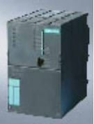
The system adopts PROFIBUS + PROFINET structure in hardware composition. 5 blocks Siemens 317-2 PN/DP CPU were used to control the public system and four sets of incinerator waste heat boiler systems respectively. CPU 317-2 PN/DP has large capacity program memory and can be used for demanding applications. It can realize distributed intelligent system based on component automation in PROFInet. It can be used as a PROFINET I/O controller for running distributed I/O on PROFINET. And together with centralized I / O and distributed I / O, it can be used as the central controller in the production line, and can be used for large-scale I / O configuration or distributed I / O structure. In addition, CPU has higher processing power for binary and floating point operations.
In this system, CPU 317-2 PN/DP through the PROFIBUS interface constitutes the control equipment of PROFIBUS network, read the data of each I/O station on the PROFIBUS bus. At the same time, it is equipped with PROFINET interface, which can communicate with PC through PROFINET to realize the high-speed data monitoring and control function with PC.

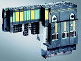
The I / O station adopts ET200S modular distributed I / O station with protection level IP 20, which can be used in Zone 2. By using "bit" templating design, the requirements of automation tasks can be accurately adapted.
In the control of motor, the traditional control method is not adopted. Instead, the SIEMENS motor protection and control device 3UF5 SIMOCODE-DP is adopted. In addition to controlling motor start and stop, it also integrates overload protection, thermistor used for motor overheat protection, grounding fault protection, turn-off protection, current value detection functions in one. 3UF5 SIMOCODE-DP connects to the PROFIBUS bus through the PROFIBUS communication port and becomes a PROFIBUS slave station to communicate with PLC.

The blower is controlled by SIEMENS frequency converter, and the air volume can be adjusted by frequency conversion. This is a scheme often used in power plant air supply system.
Three-phase AC drive system voltage source frequency conversion speed SIEMENS vector control inverter is with IGBT inverter, full digital technology with voltage intermediate loop inverter. Together with Siemens three-phase AC motors, it provides high-performance, most economical solutions for all industrial applications and applications. SIEMENS is based on the drive technology of the system. A universal and modular standard series device SIEMENS vector control series inverter is a series of universal and modular products. The power range of the standard set is from 0.55 kW to 2300 kW. The three-phase AC grid voltage that covers the whole world is 380 V to 690 V.
The operator station uses 5 IPC to monitor and operate the system. One of them monitors the public system, and each incinerator-HRSG system is monitored by an industrial computer. IPC and three PLC connect to PROFINET through network cable and switch to exchange data.
1.2 hardware configuration


1.3 control system specific control adjustment
A) public system, as shown below

The public system includes four combustion fans commonly used in incinerators, and a grate cooling water system.
The main equipment to be controlled are: start and stop of combustion fan, start and stop of three cooling fans and interlock (dual-purpose equipment), start and stop of two cooling water pumps (one with one, when the pressure of pump outlet pipe is low), and control of two ash transfer motors under ash separation baffle (work switching of two sets of conveying devices). As mentioned above, the motor in the system is mostly controlled by UNOCODE-DP.
B) general system diagram and hydraulic system

The garbage loading system is operated manually. Not included in the control system.
The control of hydraulic system mainly includes the start stop control of three hydraulic pumps.
C) 1# incinerator system
Control of incinerator system includes:
Control of three burners: including boiler start-up control, and when the furnace temperature of the corresponding measurement points can not meet the requirements of automatic combustion. (two combustor is judged according to the temperature at the two outlet of the combustion chamber).
Control of intake air valve: three main throttle used for primary air regulation are arranged under the grate. The air door opening of the front main air duct for the first three grates is adjusted according to the smoke temperature above the first three grates; the air door of the rear main air duct for the last five grates is adjusted according to the smoke temperature above the last five grates; and the air door of the rear main air duct for the last five grates is adjusted according to the smoke temperature above the last five grates. The air valve of the secondary air duct entering the secondary combustion chamber is adjusted according to the temperature and oxygen of the secondary combustion chamber to ensure that the flue gas temperature and oxygen of the secondary combustion chamber meet the requirements.
Blower (blower) control: frequency converter control. According to the furnace pressure regulation, to ensure the operation of micro negative pressure in the furnace.
Fire door, feeder and grate movement control: in accordance with the fire door opened, feed, all levels in turn forward the order of operation. The cycle time of cutting / automatic operation and grate movement can be cut.
D) waste heat boiler

The control of HRSG includes:
Control of steam outlet electric door and emergency discharge electric door. The PID regulation and the three impulse PID adjustment of the boiler water.

2. control scheme for DCS system controlled by steam turbine and auxiliaries
The control system of steam turbine and auxiliary unit in a garbage incineration power plant includes the following parts: deoxygenation water supply system, circulating water system, fuel pump house system, 1 #, 2 # steam turbine water system and ETS emergency shutdown protection system. DCS is responsible for data acquisition of these systems, as well as digital and analog control.
The whole system belongs to small units from the control scale. Therefore, the automatic control system (AS) station of DCS system only adopts a set of redundant SIEMENS 414-4H CPU. The AS414H CPU is a redundant configuration, and when the main processor fails, the backup processor immediately switches to the main processor undisturbed. The backup CPU is updated at the same time as the main central processor. The I/O system adopts 9 redundant ET200M distributed I/O stations and communicates through PROFIBUS DP. In addition, a 414-3 DP CPU is installed as AS station for the turbine ETS protection system to establish an independent ETS system. ETS is also equipped with SICAM MCP TS and SICAM DI template, with the SICLOCK TM clock generator to achieve 1ms precision SOE (event sequence recording) function. The series is equipped with an engineer station (ES) and two operator stations (OS). AS station connects to industrial Ethernet through CP443-1, and ES station and OS station connect CP1613 to industrial Ethernet.

ematic diagram of hardware system for steam turbine and auxiliaries of refuse incineration power plant
2.1 input and output point table:

