usage scenarios
Have you encountered such a problem during the on-site debugging of the equipment?
Controllers of different brands want to achieve the needs of communication, but they encounter the following situations:
-
Controller protocols of different brands are inconsistent
-
Inconsistent communication interface
-
Communication Interface Hardware Limitations
-
Unified protocol programming is cumbersome
-
The controller has permission and cannot be programmed
-
After configuration and programming, it needs to be stopped to download, and the site cannot be stopped
-
The remote controller is already running, the client does not allow changes, etc...
Don't worry, UniMAT IoT Gateway can help you with one-stop solution!
UniMAT gateway can realize the communication between controllers of different brands and different interfaces through simple configuration, which perfectly solves the above problems.
UniMAT Internet of Things Gateway
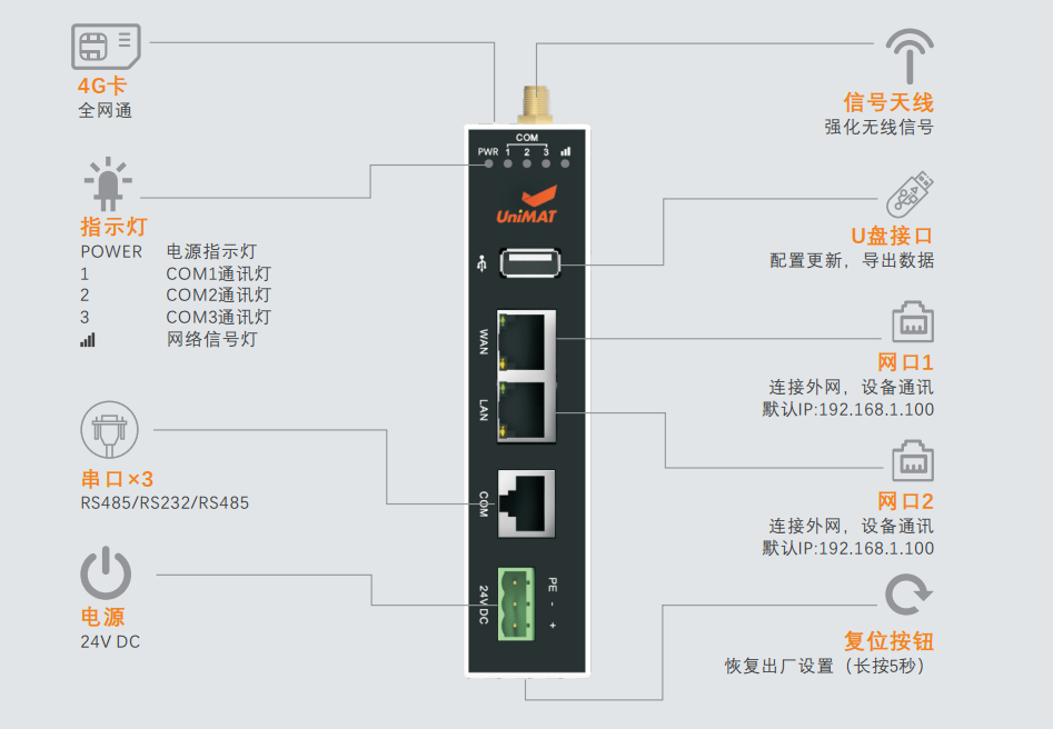
0 1 Hardware interface
-
2 Ethernet ports
-
2 RS485 ports
-
3 RS232 ports
|
SiemensSiemens |
S7-200(PPI) |
serial port |
|
S7-300(MPI) |
serial port |
|
|
S7-200 smart(PPI) |
serial port |
|
|
S7-200 smart TCP/IP client |
network port |
|
|
S7-300/400 Profinet |
network port |
|
|
S7-1200/1500 TCP client |
network port |
|
|
Mitsubishi |
Fx1S |
serial port |
|
Fx1N/2N |
serial port |
|
|
Fx3U/3G |
serial port |
|
|
Fx5U ASCIIMODE TCP |
network port |
|
|
Fx5U BINARYMODE TCP |
network port |
|
|
OMRON |
CJ/CS/CP(FINS) |
serial port |
|
CJ/CS/CP Ethernet/TCP(FINS) |
network port |
|
|
NJ/NX Ethernet/UDP |
network port |
|
|
host link |
serial port |
|
|
Delta |
DVP |
serial port |
|
AS Series Ethernet/IP |
network port |
|
|
LS |
LS_CNET |
serial port |
|
LS_CPU_DIRECT |
serial port |
|
|
LS_MASTER_K_CNET |
serial port |
|
|
LS_MASTER_K_CPU_DIRECT |
serial port |
|
|
LS_XBC_CNET |
serial port |
|
|
LS_XBC_CPU_DIRECT |
serial port |
|
|
Panasonic |
FP |
serial port |
|
Inovance |
H1U/H2U |
serial port |
|
H3U |
serial port |
|
|
H3U_Ethernet |
network port |
|
|
XINJE |
XC |
serial port |
|
XD |
serial port |
|
|
FATEK |
FBS |
serial port |
|
Modbus |
Modbus_ascii_master |
serial port |
|
Modbus_ascii_slave |
serial port |
|
|
Modbus_rtu_master |
serial port |
|
|
Modbus_rtu_slave |
serial port |
|
|
Modbus_TCP/IP_CLIENT |
network port |
|
|
Modbus_TCP/IP_SERVER |
network port |
|
|
HollySys and Belize |
LE/LM PLC |
serial port |
|
Simphoenix |
E550 |
serial port |
|
E580 |
serial port |
|
|
EP_series |
serial port |
|
|
VS500 |
serial port |
|
|
Trio |
Trio Modbus-TCP/IP |
network port |
|
DL/T645 Electricity Meter |
DL/T645-2007 standard |
serial port |
|
yudian |
AIBUS |
serial port |
Hardware that meets the appeal interface and protocol can communicate directly with the gateway, and realize data exchange between devices through data transmission.
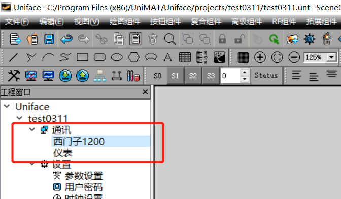
Application example 1 Instrument and PLC
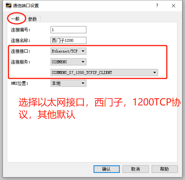
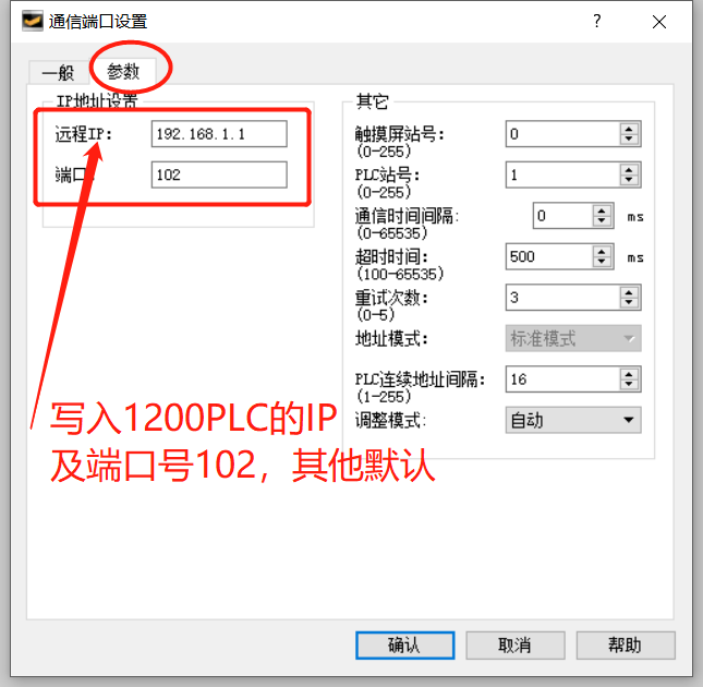
The Siemens 1200PLC control system needs to communicate with multiple instruments on site. Since the 1200CPU does not have a 485 interface, or when the 485 interface is added, it needs to be shut down to download the configuration and the scene cannot be shut down. The gateway is used to realize the configuration process of transmitting instrument data to the 1200CPU. as follows:


When the serial port is connected to the device, the address mode can be selected from standard mode and extended mode. Standard mode is one-to-one communication, one master and one slave. The expansion mode is one-to-many communication, one master with multiple slaves. In the extended mode, the slave address is written in front of the address.
If the address 4x1 of the temperature meter is the temperature value, the temperature value needs to be transferred to DB1.DBW0 of Siemens 1200.
0 2 Configure output transfer

After this setting, the gateway transmits the data of the instrument to the Siemens 1200CPU. The maximum address length can be set to 100. The maximum number of data transfers is 100. Therefore, it is best to first assign the communication area to a continuous address during transmission, which can simplify the configuration.
After configuring the configuration, save and download the configuration to the gateway, so that the data of the instrument can be stored in the 1200CPU through the gateway. Only the data transmission function of the gateway is used here, and the networking function of the gateway is not required, so the gateway does not need to plug in the card or plug in the network cable to connect to the Internet. If the gateway needs to transmit data to the cloud platform, it can be added in real-time data, refer to the Internet of Things Quick Start Documentation, which is not described in this article.
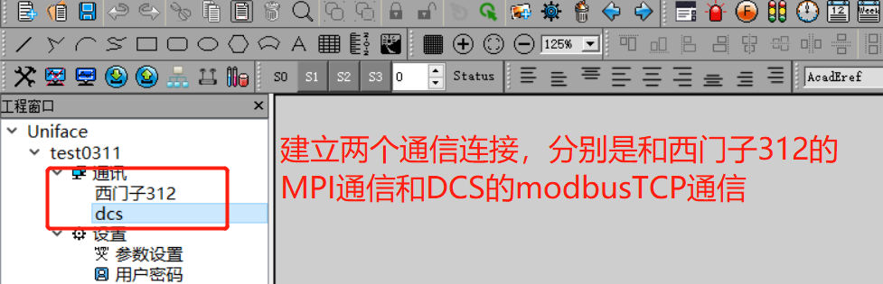
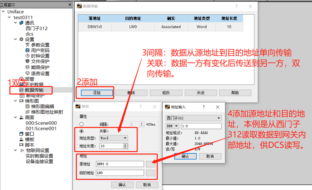
Application example 2 PLC and DCS
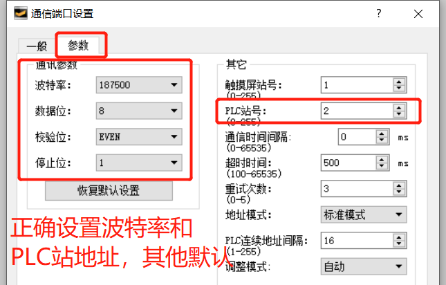
There is a Siemens 312CPU on site, and now the data in the 312CPU needs to be displayed in the central control room of the factory. The central control system adopts a certain brand of DCS system, which provides an Ethernet port and supports the protocol modbusTCP client.
The gateway can be used to communicate with Siemens 312CPU through the MPI communication port, and the gateway can be configured as a modbusTCP server for the DCS system to read data.

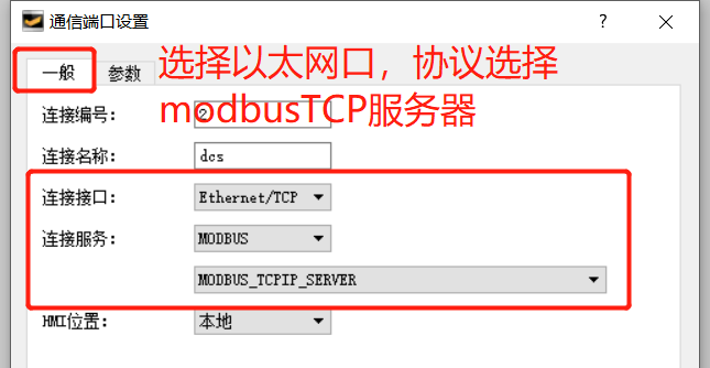
When the gateway acts as a modbusTCP server, the internal address can be read and written by other clients. The corresponding relationship between the internal address and the modbus address is as follows:
|
internal address |
Modbus address |
|
LW0 |
4x1 |
|
LW1 |
4x2 |
|
LW2 |
4x3 |
|
… |
… |
After the configuration as shown in the figure below, the DB1.DBW0 in the Siemens 312CPU is associated with the 4x1 address. DCS reading and writing 4X1 is equivalent to reading and writing DB1.DBW0.
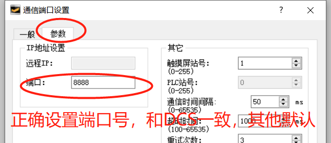
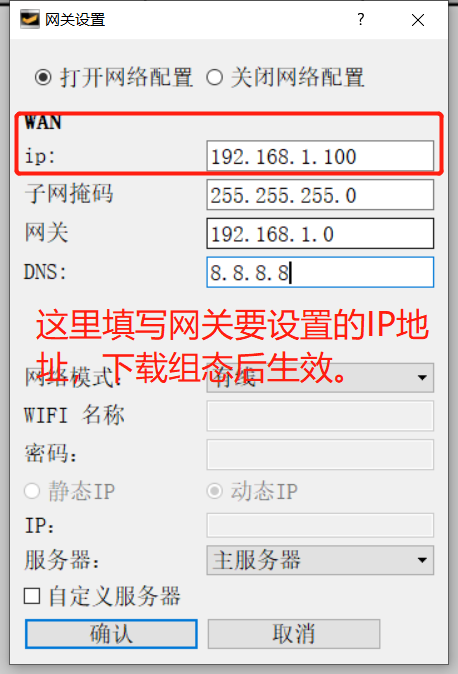
The IP address of the ModbusTCP server is the IP of the gateway, and the default is 192.168.1.100. It can also be modified in real time. The path is: Tools in the menu bar --> Gateway Settings à Open Network Configuration, and fill in the new IP.
After adding the output transmission configuration, save the project and download it to the gateway.
