
Unimat: A stable and reliable heating solution for Xiaomi's automotive factory
By UniMAT
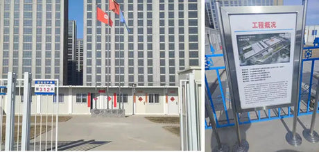
The Xiaomi Auto Super Factory is located in Yizhuang New City, Beijing Economic and Technological Development Zone, with an estimated total project investment of 63 billion yuan, a first phase...
![[Case Study] The application of UniMAT SMART PLC in the heating industry!](http://www.unimatautomation.com/cdn/shop/articles/8.29.png?v=1693301663&width=460)


![[Case sharing] Application of UniMAT SMART PLC in low-pressure boiler!](http://www.unimatautomation.com/cdn/shop/articles/5445453.jpg?v=1673402081&width=460)


